Warman's Challenge 2020
- Elena Hebden
- Dec 1, 2021
- 8 min read
Whilst completing Mechanical Design 1 at UTS, we were involved in the Warman Challenge. This is a short overview of the problem and our team's approach to solving it. I was in charge of the arm mechanism to deploy the game balls into the towers. I go through my design process below.

Problem definition
The 2020 Warman competition challenges students to design a robot to deliver ten payloads into four vertical tubes of different heights. The robot is entirely autonomous and begins in the Start/End zone with payloads preloaded. The system must navigate the field and deposit the payloads in under 120s. A 25x25 SHS obstacle is placed in the middle of the field. Points are received for each second under the time limit, as well as the number of balls deposited. The system must also begin the challenge within a size limit of 500x500x500mm.
Strategy
The team’s strategy has changed from the beginning of the project, and greatly impacts the final design decisions. Originally the robot was going to navigate the field to deposit balls into each of the four deposition towers, which varied in height. Currently, the strategy is to deposit to deposition towers B, C and D. This decision was made as it is only worth 10 points, and without the height difference, and traversing to the end of the field for one payload, the robot can be simpler and quicker.
There as a point equidistant from each of these towers B, C and D. This means that the arm can be one length once extended from the frame perimeter at the beginning of the game.
Design assessment criteria
The team's strategy helps to define functional requirements and design parameters:
1. Deposit into towers of different heights Height adjustment or testing to ensure balls will be caught in tower
2. Deposit from equidistant location Extending the arm can be one length.
3. Extend from frame perimeter Arm needs to extend out of the 500x500x500mm constraints to reach the tower.
4. Design as simple as possible Limit motors, simple mechanical structures
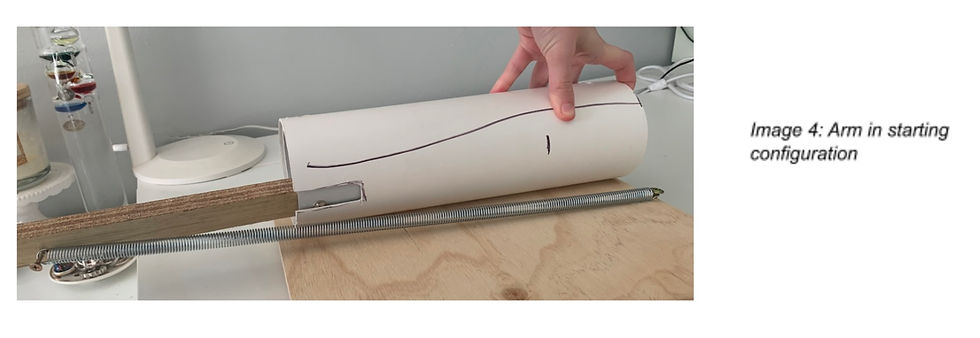
Initial Prototype
The current design is simple and mechanical, which is important for easy manufacture and keeping the weight of the robot down. It consists of two PVC tubes, one inside the other. The inner tube in spring is loaded, and when released, shoots forward to extend the tubed arm. The arm is released by a solenoid latch. This was chosen as they are very strong and can be mounted anywhere along the tubes. More in depth analysis of the solenoid latch will be in a later artefact - this is just the overall arm design concept.
These are initial sketches and a prototype of the extending arm.

Image 1: Sketches of initial idea, spring position and solenoid latch placement.


CAD - Detailed Design
Once the arm concept was approved by the group, it was time to begin detailed design. The basic structure was centered around these two tubes of PVC, one fitting inside the other. There were many different modifications and alterations along the way. The final mechanical design consisted of two PVC pipes that were cut in half so that the payloads could be dropped into it from above. The initial prototype included two tubes of 225mm, with a tab coming off the back of the inner tube in order to load the spring. After receiving feedback from artefact 1 prototype as well as beginning detailed design, it was decided to have a longer preloaded arm instead. The outer tube remains there to guide and support the dynamic tube. The feedback also suggested mounting the arm at an incline so gravity can assist, this was implemented and talked more in the mounting section later in the report.

Extensive testing was carried out to ensure the payloads could be dropped into towers B, C and D from the same height of ~300mm without bouncing out. However during this testing it was clear that the arm needed something to direct the balls downward as well as slightly slow them down for a more accurate deposition. Without something to direct the balls down, the payloads would inaccurately project off the end of the tube. To counteract this, a pvc elbow was attached to the extending tube. Once added into the assembly model it was clear that some adjustments to the elbow had to be made. Firstly, the top had to be removed slightly as it interfered with the payload storage and deposition above. Secondly the bottom of the elbow was trimmed to allow more clearance between it and the tallest deposition tower, just to ensure they would not interfere if tolerances were slightly off during build.
Adding the elbow on meant that the arm was even longer, and some adjustments had to be made to ensure it was still inside the 500mm restrictions, whilst still making sure the ball would reach the 521mm centre of the deposition towers. The major change was increasing the cut down the side of the pipe where the bolt travels as it's attached to the spring. This slit also decreases the risk of the arm flipping up.

There may be some risks with the tubes possibly twisting slightly due to the spring position, and possibly not extending fully if it were to get caught on something. However this could not be completely tested and rectified without a full build of the robot and correct mounting.
Motor Selection
The arm is powered by a spring that is retracted into the frame perimeter and held in place by a solenoid. Firstly, to select the spring we need to find the distance it will travel. From assessing the CAD model, the deflection was found to be roughly 300mm and mounting points were finalised to be roughly 70mm away from each other once the spring was resting. The mounting positions for the spring are easily modified, but this was the starting constraints for the spring to see if there was something suitable from a supplier with these needs. Century spring is a large manufacturer of springs, and their catalogue had a range of almost every possible spring you could need. As the arm was already on an incline, the spring did not need to provide much force, it was just to ensure the reliability of the arm extending. Extension spring 80248 was chosen, as it had a length of 69.9mm and an extension of 305mm.
Next to choosing a solenoid, it was important to determine the force that would be exerted on the shaft to ensure it would be strong enough. This was done simply by finding the spring rate and determining how much it would deflect.
Length of Spring = ~70mm
Max Deflection = ~ 370mm-70 = 300
Spring Rate K = 0.018 (N/mm)
F=kx
=(0.018)(300)
= 5.4 N
Therefore, the solenoid must have a holding force larger than 5.4 N.
I had never worked with a solenoid latch before so I had to do a bit of research before I could start selection. There are two types of solenoid latches: Push and Pull. As we needed the latch to start out to hold the spring loaded arm back and then retract to release the arm, a pull latch was required. The next choice was between continuous or intermittent. Intermittent solenoids are actuated for a short amount of time, then de energized. Whilst continuous solenoids can be actuated indefinitely. Therefore we need a continuous solenoid as it just needs to be pulled in once and held there for the rest of the game. Another important factor in solenoid selection was the stroke length. Difference thickness of the PVC arm is 3mm and with a bit of room for mounting clearance and tolerances, 5-10mm stroke minimum seemed appropriate.
The extra stroke length also reduced the risk of the PVC moving whilst the robot is navigating over the SHS and possibly shifting off the solenoid all together and ejecting too early.
Originally the solenoid chosen had a holding force of 35.6N and a stroke option of 10.2mm. This 12V solenoid ended up being swapped for a 6V solenoid after our electrical system was finalised. The final solenoid chosen has a holding force of 28.4 N at 20°C, so it is safe to use, and a stroke of 10mm.
Mounting and Integration
Mounting everything together, while they were small components, proved to be the most challenging as all the different requirements needed to integrate together.
Firstly to mount the PVC tubes. The shorter, wider tube is static and is the base point for mounting. This decided to be mounted on one end by a rod going through both sides of the tube, and being supported by the columns of the robot that held up the storage device above. The main front support was designed to cradle the tube. The front face has a cut in the top to fit the outer diameter of the tube and rest perfectly. Two side supports come off the side to keep the front face in place. To integrate this into the rotating base of the robot, a shallow groove was cut into the base to ensure its structural integrity. The side of one of the supports has a countersink nut protruding out of it for one end of the extension spring to be mounted.

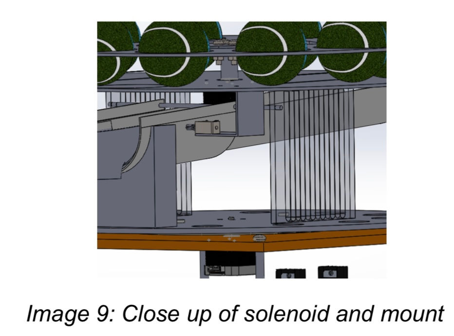
The final component to be mounted and integrated into the system is the linear solenoid. The main criteria is for it to be close enough to the PVC tube so the stroke will easily hold it back and release it. As the stroke length of 10mm was chosen, there is a bit of tolerance to play with. A simple C-style bracket was created to hold the motor. The top section is fixed to the storage container with a countersunk bolt, so it will not interfere with the movement of the payloads above. The solenoid is easy to mount as it can be placed at any point along the dynamic arm. The final mounting spot was chosen near the centre a bit close to the front of the robot. This was to allow easy access, but also close enough to the centre for cable management. Two levels of the robot rotates, so the easiest way to manage wires was to drill a hole in the MDF rotating base close to the centre to avoid tangling and interference with other components.
Bill of Materials
Table 1: Bill of Materials for the arm portion of the robot

Fasteners not included, only main body parts. MDF material included in BOM for the entire robot as it is used for the bases.
5. Discussion
5. 1 Subject Learning Objectives
These artefacts have allowed me to work toward most subject learning outcomes, with the exception of 6, as I was not involved with the software aspects of the group robot.
1. Use CAD solid modelling software to create part and assembly models
I created parts and subassemblies for the arm mechanism
2. Describe and apply the concept of design intent when creating CAD solid and assembly models
I aimed to create parts and dimension them so they could be easily altered and changed later on when designs were reviewed and revised.
4. Apply the principles of mechanism analysis and design.
Analysis of the arm was mainly completed to determine the spring and motor to use.
5. Apply good mechanical design practice to design and build a mechanical device
I have used mechanical design to define requirements and parameters, sketch out and communicate my design to team mates and then prototyping the arm to demonstrate that it would actually work. However it was not done to the quality that the final robot would have been if we did build it.
7. Communicate and document design ideas, decisions, justifications, calculations and outcomes effectively”
This artefact is allowing me to document my design ideas and justifications, and will develop further with the submission of the full report in a few weeks.

Comments